Slingsby Type 1 Falcon
Having achieved his A and B gliding certificates, Fred Slingsby was anxious to make progress. For early soaring attempts beginners needed a mild-mannered sailplane that would not respond too sharply to clumsy handling, yet had a sufficiently low rate of sink to allow sustained flight in slope lift. In 1930 there were few intermediate gliders between primary trainers and the advanced sailplanes of the experts. One type used in Germany was the Priufling, virtually a primary glider wing with a fuselage hung below it on struts. Its performance was poor and it was not very stable. A few had appeared in Britain. Giinther Groenhoff, a young German pilot already establishing a high reputation, visited the Scarborough Gliding Club in the winter of 1930, and following Groenhoffs recommendation,
Slingsby decided to build for himself, from plans obtainable through the Rhon-Rossitten Gesellschaft (RRG, the controlling body for gliding in Germany), a Falke. He was warned that it was not very easy to build, but he was confident that he could manage it. The Falke had been designed by Alexander Lippisch in 1929, and it owed almost everything to the experimental tailless sailplanes which Lippisch had been developing since 1925. Flying models with wingspans of about 4m had been flown before the first full-scale Storch was tried in 1927 with limited success. It was followed by improved versions. The Storch 4 which Groenhoff tested in 1929 was entirely satisfactory.
Stability was obtained with a back-swept wing having negatively twisted outer panels, or 'washout'. Tip winglets
and rudders gave adequate control in yaw. The main improvement distinguishing the Storch 4 was the
installation of lobate ailerons, or elevens, with their hinge line at 90° to the line of flight, rather than conforming
to the wing sweep. The wing section at the root and for the inner panels was a modified version of the Gottingen 535, but the profile was progressively changed to a strongly reflexed shape at mid-elevon, and thence to a thin symmetrical tip.
Lippisch, who was head of the technical section of the RRG, decided that if a sailplane with no tail could be made stable with a sweptback wing, then a glider
with sweepback and an ordinary tail unit as well would be even more stable, and hence exactly what the beginner required. Moreover, with such a layout the pilot would be well protected, sitting under and somewhat behind the centre of the parasol wing. An adequate soaring performance could be ensured by keeping the wing loading down, which could be done by using a large wing area with strut and wire bracing, giving a strong yet light structure. Little attention need be paid to reducing drag. Sailplanes were launched directly into the slope upcurrent by rubber bungee, and there was no need to have a good glide ratio for cross country flights. The Falke was not expected to go anywhere except gently back and forth in front of a hill. It was considered an advantage for an intermediate sailplane that it should not gain much airspeed in a dive. In the inevitable accidents it would not strike the ground so hard.
When Groenhoff met Slingsby the Falke was in production in Germany. There was already one in England; it had been imported for publicity purposes
by the J. Lyons tea company. Gliders at this time were always built of wood. The timber normally used in Germany was pine. Spruce was more expensive and offered only slight advantages. Aircraft-quality birch plywood was readily available. Cold-water casein glues were approved for aircraft construction and, provided the joints were kept dry, were perfectly satisfactory but damp joints could be quickly destroyed by fungus. Accordingly, numerous drainage and ventilation holes were incorporated at all points in the structure where moisture might otherwise accumulate. Mild steel fittings and brackets were bolted to the timbers after painting with zinc chromate. Steel control cables were guided round pulleys and through fibre fairleads where required. The Falke fuselage, of hexagonal cross-section, was a wooden framework of six curved longerons with cross-frames and diagonal braces, with plywood skinning in front and fabric covering aft of the cockpit.
As usual where wooden members butted together substantial plywood 'biscuits' or solid corner blocks were used to cany the loads through the joint. The undercarriage comprised a rubber-sprung main skid of ash, and a tailskid. An open hook was fitted under the nose for bungee launching. The strut-braced tail unit was simple, but the wing was very complicated. The twro spars, swept at 12.5°, were built-up box sections. The upper and lower pine flanges had large 'bird-mouthed 1blocks filling in wherever fittings had to go, particularly at the root ends and the strut end points. Both sides of the spars were faced with plywood. The wings had a slight 'gull' kink, enough to complicate construction without having any measurable effect on stability or handling. To make each wing rib, an outline of 5mm square strip wood was laid in a jig, being steamed where necessary to conform without strain to the aerofoil section outline. Uprights and diagonals were fitted inside this form, and 1mm plywood biscuits and webs were then glued over all the joints, after which a duplicate 5mm
square strip outline was laid into the jig with matching uprights and diagonals, and glued. This split-rib structure, which persisted for many years in German
sailplane construction, prevented sideways distortions of the ribs when they were under the tension of doped fabric covering. The wing chord was constant over the inner panels, which allowed some saving in work, but for the tapered and reflexed outer wing panels every rib differed from the next.In the Falke and other training gliders, the plywood covering the front of the wing was little more than an unstressed fairing. Each rib was made in one piece from leading edge to trailing edge and slid into place over the completed spars before gluing. Because the plywood was glued only to the ribs, not to the spar flanges, it added little strength to the wing as a whole. For torsional rigidity a two-spar structure with internal diagonal cross-struts was used. Every third rib was a compression member requiring its own jigging. The wing spars met on the aircraft centre line with simple pin joints, the rear pin also connecting with the pylon behind the cockpit. The front spars had separate connections to the braced vertical cabane struts on either side. The V struts restrained the wings from folding up or down under load, and provided additional bracing against torsion. A detachable plywood fairing covered the gap in the wings at the centre. The aileron control cables ran externally up the side of the fuselage, entering the wing just behind the forward cabane strut. The elevator cables also were external for part of their length. There was a steel bracing cable from the nose to the struts near their outer ends.
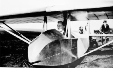
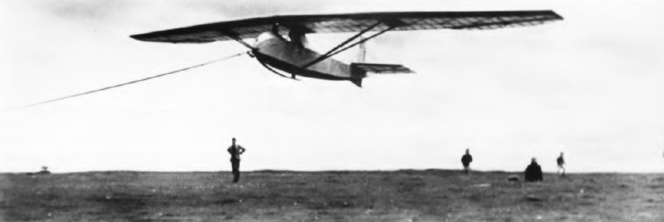
Fred Slingsby about to bungee launch in his Falcon 1
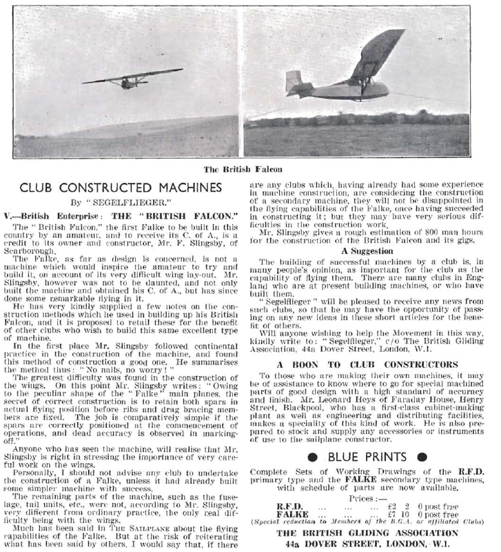
Slingsby completed his Falke in the spring of 1931. He stated that roughly 800 man-hours were required. Probably furniture production in his factory was much reduced for the preceding months. On completion the sailplane, in clear-doped finish and glossy varnish, was christened British Falcon. Slingsby made his first flight at Levisham Moors after a bungee launch powered by schoolchildren, this was a flight of some 12 minutes, his first 'soaring' flight. Another pilot crashed the Falcon badly on its second flight. After repairs, Slingsby toured the country in search of good soaring sites, gaining his C soaring badge in September at Ingleby Greenhow and competing very successfully in the 1932 National Championships at Ireleth, near Askam-in-Furness, Lancashire. There were seven competing aircraft. The Falcon logged nearly 7hr total flying time during the five day meeting. Mungo Buxton borrowed it to break the British distance record with a 20km slope-soaring flight to Lake Coniston. To put this into perspective, in the German championships that year there were 60 sailplanes. Cross-country flights of 150km (93 miles) were made, but Groenhoff, Slingsby's adviser of 1930, was killed in one of two fatal accidents.
It was remarked that the Falcon flew itself, but handled easily when it was required to manoeuvre and was capable of soaring well. It was a great builder of
confidence for nervous pilots. Rigging was rather a struggle, and it suffered from lack of upward view when turning. This became important as the soaring
ridges grew more crowded, but for its purpose it had few rivals. Slingsby announced later in the year that he would build a Falcon for anyone for £95.
The second Falcon, which Slingsby later counted as his Type 2, was built to the order of Espin Hardwick, a stockbroker who played an important role in the
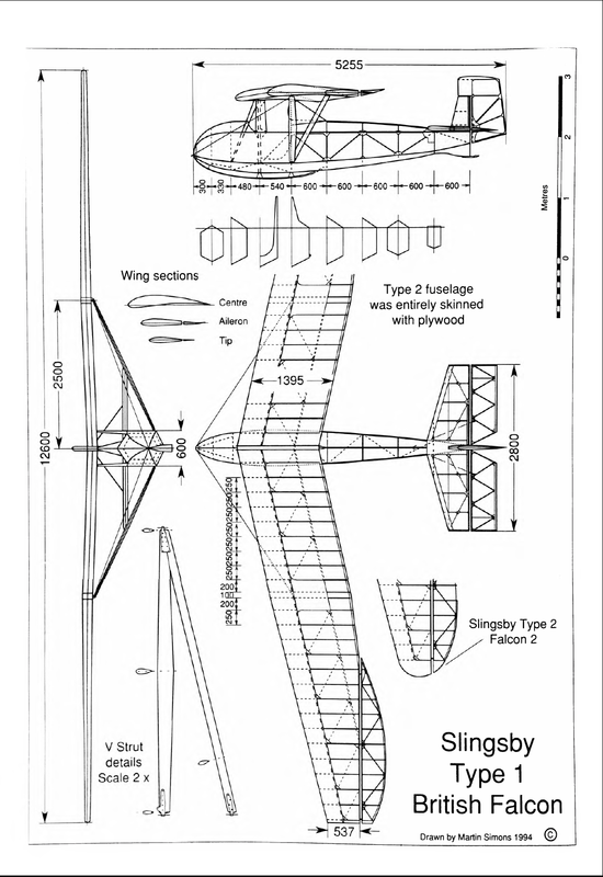
development of British gliding. Falcon 2 was flying by October 1933, Hardwick obtaining his C soaring badge at a Sutton Bank meeting in that month. The Type 2 had rounded wingtips which improved its performance slightly, and its fuselage was entirely skinned with plywood. Hardwick suffered from a spinal deformity, so most ordinary sailplane cockpits must have been extremely uncomfortable for him. His Falcon had extensive padding and movable elbow rests, and it also possessed instruments, which very few other sailplanes in Britain did in 1933.
It was remarked that the Falcon flew itself, but handled easily when it was required to manoeuvre and was capable of soaring well. It was a great builder of
confidence for nervous pilots. Rigging was rather a struggle, and it suffered from lack of upward view when turning. This became important as the soaring
ridges grew more crowded, but for its purpose it had few rivals. Slingsby announced later in the year that he would build a Falcon for anyone for £95.
The second Falcon, which Slingsby later counted as his Type 2, was built to the order of Espin Hardwick, a stockbroker who played an important role in the
development of British gliding. Falcon 2 was flying by October 1933, Hardwick obtaining his C soaring badge at a Sutton Bank meeting in that month. The Type 2 had rounded wingtips which improved its performance slightly, and its fuselage was entirely skinned with plywood. Hardwick suffered from a spinal deformity, so most ordinary sailplane cockpits must have been extremely uncomfortable for him. His Falcon had extensive padding and movable elbow rests, and it also possessed instruments, which very few other sailplanes in Britain did in 1933.
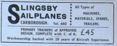
Slingsbys first advert in 'The Sailplane and Glider' Vol4 No 18 November 1933
Slingsby soon decided that there was a future in glider manufacture, and he began to advertise under the heading, 'Slingsby Sailplanes, Scarborough'. The
decision to abandon furniture manufacture altogether came in 1934 with a temporary shift to the disused Scarborough Corporation tram sheds, where there was more space for glider assembly. Eight more Falcons were built during the next few years after the move to Kirbymoorside, making a total of ten including the Falcon 2. (Although Fred latter remarked in an article that 12 were built?). One was exported to Canada. Three, including Slingsby's original, were written off at various gliding sites before the outbreak of the Second World War. The rest probably survived to be impressed for use by the Air Training Corps (ATC). One of these, piloted by a cadet, met its end in collision with a sheep at Camphill in Derbyshire about 1944. Others doubtless perished at other ATC schools. One was rebuilt with a flying-boat hull for the ATC to fly from Lake Windermere in 1943, and survives at the Windermere Steamboat Museum. Espin Hardwick's Falcon 2 was ceremonially burned at the Long Mynd following his death in 1955.
Mike Russell provided the initial inspiration for the construction during 1984-85 of an entirely new fully airworthy Falcon 1 by Ken Fripp's Southdown Aero
Services at Lasham, using the original drawings rescued from Slingsby's loft. There were substantial contributions of work and financial support from John
Sproule. The first flight was made in August 1986, with Derek Piggott at the controls. This Falcon, the only extant airworthy example, appears occasionally at
vintage glider meetings in its clear-doped and varnished finish like the original Slingsby Type 1.
Text modified from Martin Simons original in 'Slingsby Sailplanes'
Technical Information
Falcon 1 data
Dimensions
Wingspan 12.6m (42ft)
Wing area* 18.48m 2 (198.9ft 2)
Aspect ratio
Sweepback
Length over all
Wing sections
Root
Mid-aileron
Tip
8.(>
12.5°
5.26m (17ft 5in)
Gottingen 585 modified
Special reflexed
Symmetrical
Weights (approximate)
Tare 140kg (3081b)
Flying 230kg (5061b)
Wing loading 12.45kg/m 2 (2.51b/ft 2 )
* The wing area given here was estimated from the
factory drawings. It differs from figures previously
stated, with consequent variations in aspect ratio and
wing loading. The German Falke was advertised with
tare weight 120kg (2651b).
The British
From article BRITISH DESIGN AND CONSTRUCTION.
Sailplane and Glider vol3 no 19 oct28 1932
Perhaps the best example of British construction using
a German design is the FALCOX which put up such a
pleasing performance at the recent Competitions at
Askam. Apart from certaiu minor modifications, tbis
machine, which was constructed by lIfr. Sling-shy, of
Scarborough, is a copy of the FALKF:. Nevertheless, its
excellent performaHce is a very great testimonial to Mr.
Slingsby's constructional work.. During the first test
flight tIe soared tht madline for over 12 minutes-incirlentally
his first soaring- flight. It is so stable that it
will fly " hands off" for really long periods. Mr. Buxton
found this useful during his recent distance flight from
Askam ta Coniston when he was able to get out his map
and calculate hom the contours, distance and estimated
gliding angle what. height he would require to fly back
on the Coniston ridge.
The F,ILCON has been very thoroughly tested under
varying conditions. Mc Slingsby wanders with it all
. over the country, rarely USing the same site two weeks
in succession. Its robust construction and good performance
render it eminently suitable for advanced training
purposes. We understand that its owner is prepared to
COIH;truct a similar machine to sell at £95.